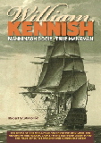
The illustration at the head of this page and many others on this site is taken from William Kennish’s 1837 book “ A Method of Concentrating a Broadside...” and is described by William below. The image of his Marine Theodolite directly below is taken from his medal-winning Society of Arts Manufactures and Commerce paper published in 1832.
The two Ships in the Frontispiece are supposed to be in chase. The headmost one, finding the stern ship within the distance (500 yards) of No. 5 Fire, shortens sail by taking in studding sails, clewing up the courses and royals, which help to bring the ship on an even keel and also to deaden her way ; the ship is then partially bought to the wind, sufficient to bring the line of sight of the instrument on the bow of the enemy in her water line, pointed out by the dotted lines from the poopdeck of the headmost ship to the water-line of the enemy. The small circle on the gunwale represents the Marine Theodolite, the height of which from the water is known, and by which the distance between the two ships is ascertained. Previous orders are given to the helmsman to reverse the helm. The moment the broadside is discharged, sail is again made, and the ship brought to her former course.
The manoeuvre here represented is intended that the ship chased is of an inferior force such as a frigate, by which she may be enabled to extricate herself from falling into the hands of the enemy, should the latter be capable of overreaching her; and if the manoeuvre is well performed, there is no doubt of its success. The reason I have shown the ships of equal force is, that a three-decker shows my plan to greater advantage.
All of the text and illustrations from “Concentrating a Broadside...” are faithfully and accurately reproduced in the current book which brings these back into publication for the first time in 164 years. The figure below is the 1837 version of the 1828/32 theodolite - much refined from its earlier practical prototype.
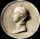
The Gold Isis Medal of the
Society for Arts, Manufactures
and Commerce 1832
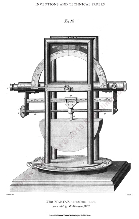
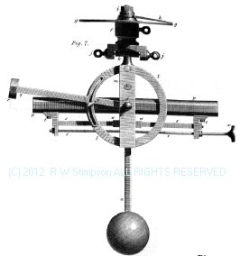
This view of an enhanced version of the Marine Theodolite is taken from William’s Book published in 1832. This is far more sophisticated than the original developed on the American station and which appeared iin his RSA paper of that same year.
It is not clear if this version was ever constructed, as no records of this have survived beyond his book, and this was created after sea trials had been completed.
The marine theodolite tube “T” is aligned to point at the opponent ship’s waterline by rotating adjusting screw “A” to move counterweight “B”. The tube and weight move together to sit at the correct angle at any ship lee or list angle. The range is then called out by the Gun commander using the theodolite and the gunners set the Quoin elevation according to the deck and the range.
To aim the guns to a single point at this elevation, each gun had a Breast-Piece with uniquely drilled sets of alignment holes into which a pair of pins can be dropped in to fix the range at 300, 400 or 500 yards.
When the target vessel is in range and the ship vertical, ropes are pulled to ring bells on all decks - at which all guns are fired,
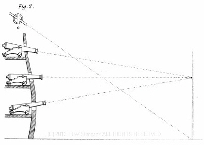
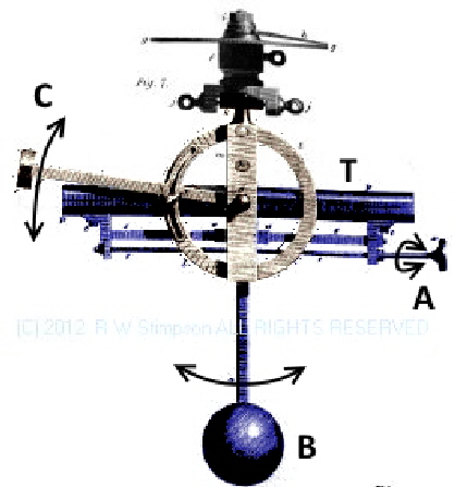
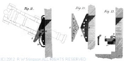
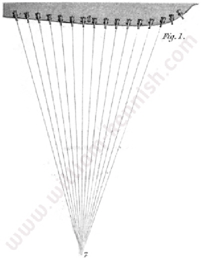
The marine theodolite was mounted on a gimbal and had a counter-weight to ensure the elevation sight will always be accurate irrespective of the roll of the vessel; if the elevation is set as the ship passes through vertical and the same point is used to ring the linked deck bells to signal firing, the range and targeting will be accurately reproduced.
The target sighting tube T was adjusted so that the target ship could be seen through it when the counterbalance weight B was located vertically. Adjuster A moved the ball and arm B along it, varying its inclination. Alignment sight C was then lined up with T at the correct position, which would happen every time B became vertical. This would allow the gun commander (typically the captain) to issue range instructions to the guns; they would set breast-pieces and quoins accordingly. When the ship rolled to the vertical position, C would line up with T and the command to fire would be given - pulling sharply on a rope linked to bells positioned on each gun deck. The guns would then issue a salvo directed to a single point.
Family history recounts also that William was involved or associated shortly before his death in 1862 with the development of USS Monitor - the first Turreted gun ship. Currently no independent written records have been located to verify this very interesting story!
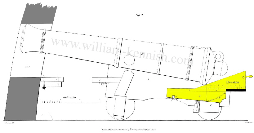
This view above shows the quoin highighted in yellow. It is an adjustable wedge to set the elevation angle of the gun.
It is very quick and simple to fit and set.
The handle to the right can be lifted, allowing the triangular wedge to be moved and set closer to the gun trunnion (a lower elevation) or further way (for a higher elevation).
Markings on the side show range.

Site Copyright Statement © 2011-2022 Robert W Stimpson
